Measuring EFHW Transformer Efficiency
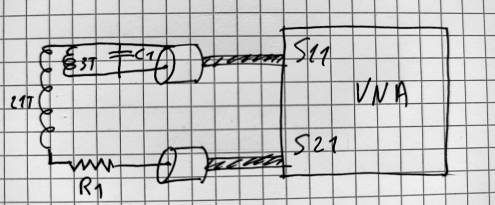
In this article, we will explore how to measure the efficiency of a transformer for End Fed Half Wave (EFHW) antenna, using a Vector Network Analyzer (VNA). The transformer is placed in series with a resistor \(R_1\), which acts as a virtual antenna. By analyzing \(S_{11}\) and \(S_{21}\) parameters, we can calculate the insertion loss and ultimately determine the transformer's loss and efficiency.

Notes before starting
- Always double-check the signs of gains and losses. Remember, a negative gain represents a positive loss.
- Keep all cables around the transformer and resistor as short as possible to minimize unwanted parasitic effects.
- Ensure accurate calibration of the VNA before starting measurements. Calibration must be performed precisely at the connectors where the transformer will be connected. Any differences (adapters, cables...) between the calibration setup and the measurement setup can lead to biased results.
- Choose the resistor \(R_1\) to match your transformer's specifications. For example, use a 2450-ohm resistor for a 49:1 transformer, a 2700-ohm resistor for a 54:1 transformer, etc.
In reality, the impedance of an EFHW (End-Fed Half-Wave) antenna is not fixed and rarely exactly 2450 ohms or 2700 ohms. The actual impedance depends on many factors, including the height of the antenna above the ground, the surrounding environment, the operating frequency, and the quality of the ground system. These variations mean that the resistor used in testing is an approximation, representing a nominal impedance for the transformer design.
While the resistor \(R_1\) provides a controlled and repeatable testing condition, it does not perfectly replicate real-world scenarios. Therefore, the measured efficiency and losses should be interpreted as indicative of performance under idealized conditions, not as absolute values.
Step 1: Setup and Understanding the Compensation Factor
The Circuit
The transformer is connected in series with a resistor \(R_1\). The resistor introduces a known loss, which we must account for to isolate the transformer's performance.
Compensation Factor
The compensation factor (\(C_f\)) accounts for the loss caused by \(R_1\). It is calculated in decibels using the formula:
\[ C_f = 10 \cdot \log\left(\frac{R_1}{50}\right)\]
This factor compensates for the difference between the resistor \(R_1\) and the standard 50-ohm impedance.
Step 2: Calculating Insertion Loss
\(S_{21}\) Gain
The \(S_{21}\) parameter (also known as forward transmission gain) is measured directly by the VNA. Since it's a loss, you are waiting for a negative value here.
Total Insertion Loss
The insertion loss combines \(S_{21}\) gain and the compensation factor:
\[ \text{Insertion Loss} = - S_{21}\,\text{gain} - C_f\]
Step 3: Relating Insertion Loss to Mismatch Loss and Transformer Loss
Insertion loss can also be expressed as the sum of mismatch loss and transformer loss:
\[ \text{Insertion Loss} = \text{Mismatch Loss} + \text{Transformer Loss}\]
To calculate mismatch loss, we use the reflected coefficient (\(\Gamma\)) derived from \(S_{11}\):
\[ \Gamma = \frac{S_{11\text{vSWR}} - 1}{S_{11\text{vSWR}} + 1}\]
\[ \text{Mismatch Loss} = 10 \cdot \log\left(1 - \Gamma^2\right)\]
With mismatch loss known, the transformer loss can be isolated:
\[ \text{Transformer Loss} = \text{Insertion Loss} - \text{Mismatch Loss}\]
Step 4: Calculating Efficiency
The efficiency (\(\eta\)) of the transformer is defined as the ratio of transmitted power to the through power:
\[ \eta = \frac{P_t}{P_{through}} \cdot 100\]
Transmitted Power
Transmitted power (\(P_t\)) is calculated from the insertion loss:
\[ P_t = 10^{\frac{\text{- Insertion Loss}}{10}}\]
Reflected Power
Reflected power (\(P_r\)) is calculated using the reflected coefficient:
\[ P_r = \Gamma^2 \cdot 100\]
Through Power
The through power (\(P_{through}\)) is the remaining power after accounting for reflection:
\[ P_{through} = 1 - \frac{P_r}{100}\]
Summary of Steps
- Measure \(S_{11}\) and \(S_{21}\) using the VNA.
- Calculate the compensation factor (\(C_f\)) based on \(R_1\).
- Determine insertion loss using \(S_{21}\) loss and \(C_f\).
- Derive mismatch loss using \(S_{11}\) and calculate the reflected coefficient (\(\Gamma\)).
- Compute transformer loss by subtracting mismatch loss from insertion loss.
- Calculate transformer efficiency using transmitted and through power.
By following these steps and equations, you can accurately measure the performance and efficiency of your transformer.
Alternate Method: Back-to-Back Transformer Measurement
Another method to measure the efficiency of a transformer is by using two identical transformers connected back-to-back. This configuration allows you to measure the combined loss of the two transformers. Since the transformers are identical, the loss for each transformer is approximately half of the total measured loss. Efficiency can then be calculated based on this loss. This method avoids the complications introduced by the resistor and is particularly useful for evaluating the transformer's intrinsic performance without external components. However, it requires a second identical transformer and precise matching between the two.


