Improving My EFHW Transformer with a Lightweight Ferrite Core
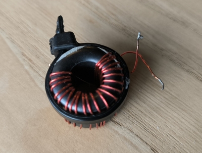
Following recommendations on the SOTA Forum, I spent some time experimenting with toroids to improve the performance of my End-Fed Half-Wave (EFHW) transformer. My goal was to achieve better efficiency while keeping the device lightweight for portable operations. Previously, I was using an FT114-43 toroid, but I have now upgraded to the Fair-Rite ferrite core 2643625002, which I’ve found to be an excellent choice for this application.
Interestingly, this ferrite core has already been featured in my blog in a common-mode choke build. Its versatility and lightweight properties make it perfect for both purposes.

The Recipe
Here are the key specifications for my new EFHW transformer:
- Core: Fair-Rite 2643625002 ferrite
- Primary winding: 3 turns (center-tapped)
- Secondary winding: 22 turns
- Capacitor: 100 pF across the primary winding
- Wire: 26 AWG enameled wire
After numerous experiments, I settled on a 54:1 turns ratio as it provided the best performance with my ~20 m long EFHW antenna. This ratio was determined to match the impedance of the antenna setup most effectively. I aimed to wind the wire neatly and uniformly to minimize loss.

Impedance Matching: A Nuanced Challenge
Before measuring the performances with a VNA, we need to select a resistor \(R_1\) to match the expected impedance of the EFHW antenna. For a 49:1 transformer, a resistor of 2450 ohms is often used, while a 54:1 transformer corresponds to approximately 2700 ohms. However, in reality, the impedance of an EFHW antenna is highly variable, depending on several factors:
- Antenna length: Slight variations in wire length can change the impedance significantly.
- Environment: Proximity to the ground, nearby objects, and even vegetation can alter the antenna's impedance.
- Operating frequency: The impedance of the EFHW antenna is not constant but varies across the operating band.
Therefore, the resistor \(R_1\) serves as a reasonable approximation for testing, but it cannot perfectly replicate real-world conditions. This variability underscores the importance of optimizing the transformer for a range of impedances rather than a fixed value.
Performance Testing
To evaluate the transformer's efficiency, I used the method described in a previous article. For testing, I connected a 2675-ohm resistor to simulate the antenna's impedance. I calculated the compensation factor to be 17.28 dB for this resistor.
Test Results:
| Frequency in MHz | S11 vSWR | S21 gain in dB | Insertion loss (dB) | Transmitted power | Reflected coeff | Reflected power % | Through power | Dissipated power % | Mismatch loss dB | Transformer loss dB | Overall Efficiency % |
|---|---|---|---|---|---|---|---|---|---|---|---|
| 7.1 | 1.15 | -17.66 | 0.38 | 0.92 | 0.07 | 0.49 | 1.00 | 7.9 | 0.02 | 0.36 | 92.1 |
| 10.1 | 1.22 | -17.63 | 0.35 | 0.92 | 0.10 | 0.98 | 0.99 | 6.8 | 0.04 | 0.30 | 93.2 |
| 14.1 | 1.30 | -17.62 | 0.34 | 0.93 | 0.13 | 1.70 | 0.98 | 5.9 | 0.07 | 0.26 | 94.1 |
| 18.1 | 1.27 | -17.66 | 0.38 | 0.92 | 0.12 | 1.41 | 0.99 | 7.0 | 0.06 | 0.31 | 93.0 |
| 21.1 | 1.23 | -17.76 | 0.48 | 0.90 | 0.10 | 1.06 | 0.99 | 9.4 | 0.05 | 0.43 | 90.6 |
With over 90% efficiency across the tested bands, this transformer shows a significant improvement over my previous FT114-43-based design, which had about 80% efficiency.
Conclusion
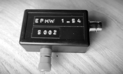
This new EFHW transformer demonstrates excellent performance, achieving efficiency gains of over 10% compared to my older design. It makes an excellent choice for portable and SOTA enthusiasts, weighing only 36g when built in an ABS case equipped with BNC and banana plug connectors


